


DESIGN AND IMPLEMENTATION OF AN EFFECTIVE VOICE ALARM-PUBLIC ADDRESS AND BACKGROUND MUSIC SYSTEM WITH EN-54 STANDARD (PAVA SYSTEM)
1.1 SCOPE:
This Blog describes the minimum engineering Requirements and scope of the Voice Alarm & Public Address/Background Music System for many hotels or commercial buildings as per applicable codes, standards and industry best practices.
This Blog constitutes technical and engineering specifications for the PAVA & BGM.
2.0SYSTEM DESCRIPTION AND DESIGN REQUIREMENTS:
The Public Address (PA) paired with Voice Alarm (VA) system is specifically designed to assist the effective evacuation of an area or building during an emergency. Oftentimes these are paired with the fire alarm system. The PAVA system incorporates elements of a public address one and is used for mixed entertainment/emergency purposes.
2.1PRIMARY FUNCTIONAL REQUIREMENTS OF PAVA SYSTEM:
Provide a secure method of voice reproduction
Deliver emergency recorded messages and/or alarm bells.
Deliver emergency live announcements to circuits/groups (i.e. EHS/Fire Officer).
Transmission of alarm signals in the event of a fire or other disaster, as well as for public announcements and playing music, an emergency audio warning system or a voice alarm system with self-monitoring functionality and alarm criteria to be installed in compliance with EN standards.
The purpose of the system is to quickly evacuate people in an orderly manner via escape routes
2.2 DESIGN CRITERIA OF PAVA SYSTEM
In total, required loudspeaker circuits and expandable up to the required programmable, monitored loudspeaker circuits should be available as well AUX inputs and XLR inputs and more than one call stations for remote signaling and Evacuation messages. (we will consider 128 circuits here for reference) The PAVA system can be designed for single building which requires up to 2 channels of audio simultaneously routing for paging and background music / messages, extendible to approx. 100 speaker line capacity and within 1 KM distance for all controls and audio transmission. All basic functionalities should be plug and play as well as PC (TCP/IP) interface for advanced functional requirements by authorized field engineers for configuration and commissioning
3.0STANDARD REFERENCE AND DESIGN PARAMETERS:
The following are the reference and design parameters considered for this blog:
3.1LIST OF RELEVANT STANDARDS TO BE REFERED FOR DESIGN OF VOICE ALARM SYSTEM: -
| Sr. No. | Standard No. | Description |
|---|---|---|
| 1 | EN54-16 (Voice alarm control and indicating equipment) | Voice alarm controls and indicating equipment like amplifiers and mixers which output voice alarm media to speakers |
| 2 | BS 5839-1/ EN60849 (Sound Systems for Emergency Purposes) | Code of practice for design, installation and commissioning and maintenance of systems in non-domestic premises |
| 3 | BS7827 (Design, Maintainance & operating specifications of Emergency sounds for large public buildings | Designing, specifying, maintaining and operating emergency sound systems for sports grounds, large public buildings for life safety |
| 4 | NFPA 72 Chapter 24 (Emergency Communication Systems) | Monitoring of speaker integrity, specified warning tones, priority messaging hierarchy, intelligibility, default emergency sound levels |
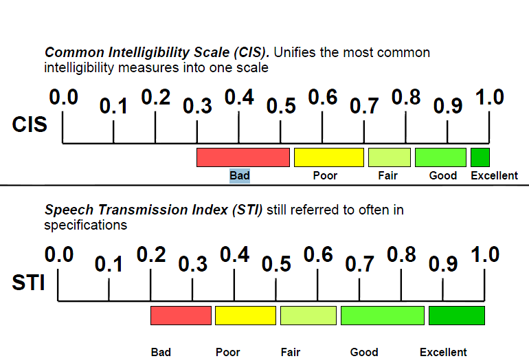
3.2 LOUD SPEAKER SELECTION, PLACEMENT AND INTELLIGIBILITY REQUIREMENTS:
The messages must be intelligible (clearly heard and understood)
Speakers need safety features in order to comply with the standard
Ceramic terminal connection blocks, Thermal fuse
Cabling requirements same as fire alarm sounders.
Intelligibility is defined as meeting CIS (Common Intelligibility Scale) of 0.7 (STI of 0.5) or greater (Refer Fig:3.2.1)
Can be measured using electronic test equipment (Rapid Assessment of Speech Transmission Index RASTI) (Refer Fig:3.2.1)
3.3 DESIGN PARAMETERS TO BE ADDRESSED:
Sound pressure level (SPL) & intelligibility
Number of inputs.
I. Audio Microphone II. Fire Alarm Dry contacts III. Zone Paging microphones IV. Background MusicNumber of Outputs (Zones)
Single or phased evacuation messages
Distribution, Centralized (Central Rack) or De-centralized (Multiple field racks)
Audio Matrix Configuration
Source/priority/destination
Amplifier selection and efficiency: Class A/B, Class D
Speaker Selection for PA or BGM
Even Speaker distribution to avoid excessive output or blind spots
I have made a Pre-NOC check as best practice for reference of fellow industry professionals:
3.4 SOUND PRESSURE LEVEL CALCULATION FOR EMERGENCY EVACUTION PUBLIC ADDRESS SYTEM:
Typical speaker sensitivity: 90 dB at (1m, 1 watt) of input power Max distance from speaker : 5m Loss in db=20Log x (x=distance from the speaker or source of sound) Refer below loss chart :
Relative dB at 1m = 0 , Relative dB at 5m = 14
Ceiling mounted loudspeakers:
Audible SPL from farthest reference point = (90-14) = 76 dB
Wall Mounted loud speakers:
Audible SPL from farthest reference point = (96-14) = 82 dB
Note: The design target is for the evacuation message to remain >=15dB above general ambient sound or 5dB above maximum expected ambient sound.
3.5 LOUD SPEAKER DESIGN PARAMETERS:
Meet or exceed a CIS of 0.7; Speech Transmission Index (STI) of 0.5 STI : A measure of how well a broadcast can be understood. 1 = best, 0.1 = worst RASTI : Rapid Assessment of Speech Transmission Index Computer based programme using coded digital “noise” Affect of signal to noise, reverberation, time delays (echo)
4.0 SYSTEM DESCRIPTION:
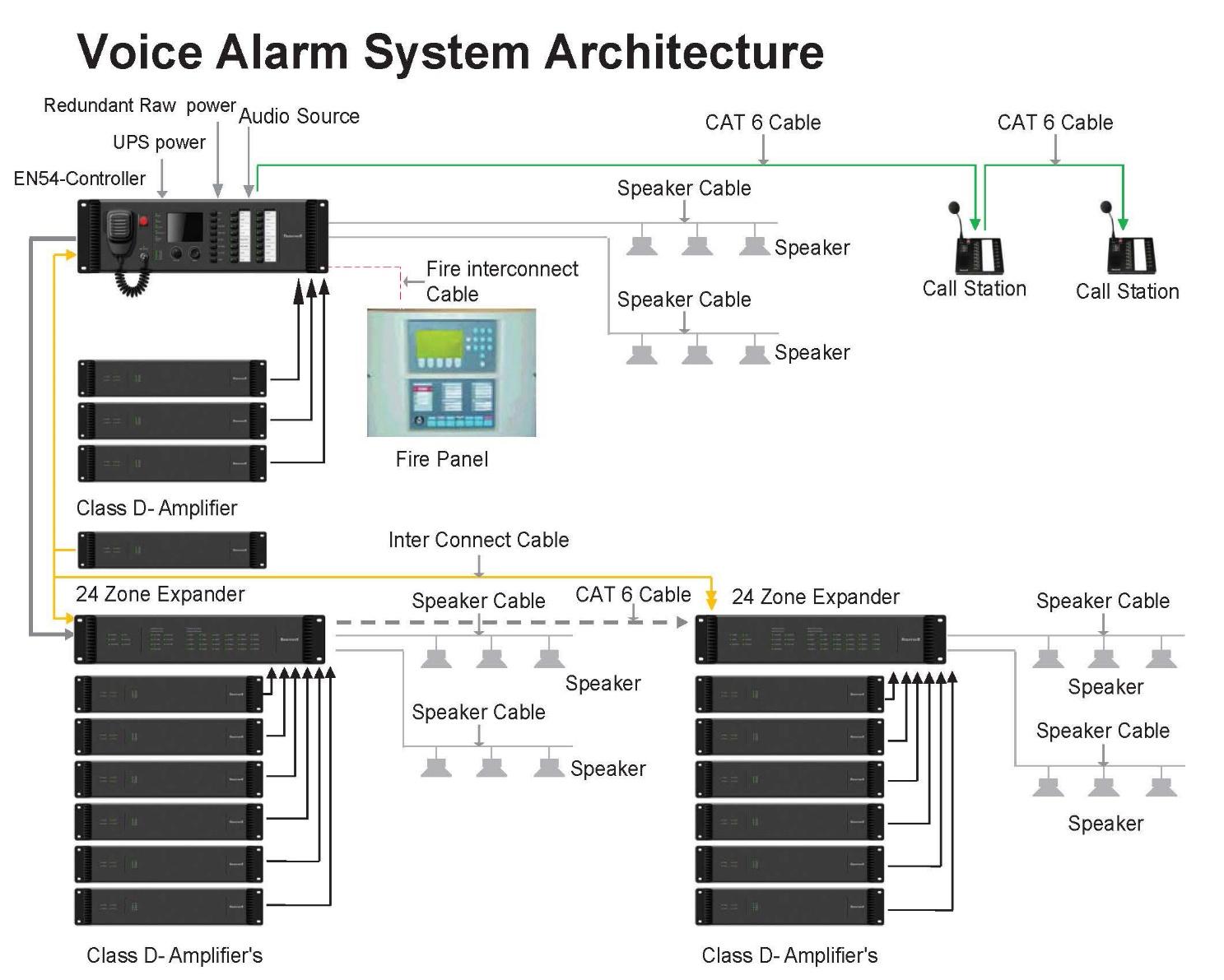
4.1 PAVA SYSTEM ARCHITECTURE:
The Voice alarm system shall be the combination of Public Address + Fire Interface + Fault Monitoring + Voice message storage + system cabling suitable for circuit integrity The system shall be as per the schematic of system architecture as shown in Fig: 4.1.1
4.2 FIRE ALARM SYSTEM INTERFACE REQUIREMENTS:
The following are the requirements of the fire alarm system interface to the PAVA System:
Dry contact relays in the fire panel selecting zones for evacuation/alert When fire alarm activates, fire alarm interface sends data to matrix, triggers emergency message. The voice alarm is a separate bus consisting of loudspeakers triggered automatically by the fire alarm Any voice and/or alarm message can be recorded and stored Voice Alarms shall be as per the BS standard BSEN60849
4.3 SYSTEM CHECK LIST:
SYSTEM INPUTS: MESSAGES: i) Evacuate ii) Alert iii) Test iv) Security v) Other
MICROPHONES : i) Multiple button microphone ii) Single button microphone iii) Fireman’s emergency microphone iv) Rack mounted microphone v) Custom microphone (ie panel mount)
BACKGROUND MUSIC:i) CD Player/Tuner/Blue tooth source
Fire alarm interface Telephone interface (optional)
4.4 DEMAND CALCULATION:
Demand calculations should be made considering different areas with or without false ceilings and the type of speakers used:
| Speaker Zoning | Separate zone circuit per floor for PA Separate BGM circuit for Defined floors and areas |
| Design Density | 4 To 5 METERS |
| Sound Pressure Level at 1w (1m& 1kHz) | 90dB (for ceiling mount) 96dB (For wall mount) |
| Frequency Range | Ceiling speaker: 125Hz -16Khz Wall Speaker: 110Hz -15Khz Ceiling BGM speaker: 65Hz-20Khz |
| Power Taps | Ceiling speaker: 3W Wall Speaker: 6W Ceiling two-way BGM: 15W |